Introduction
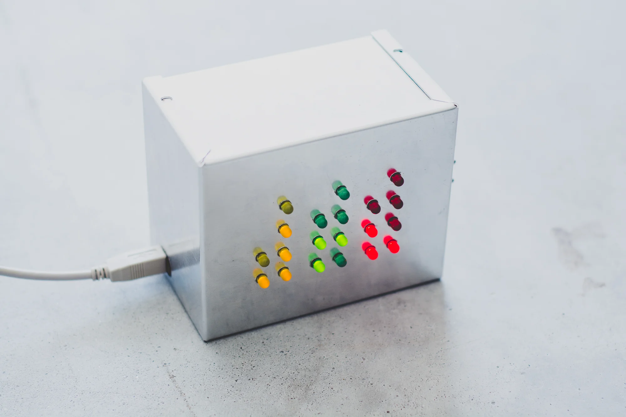
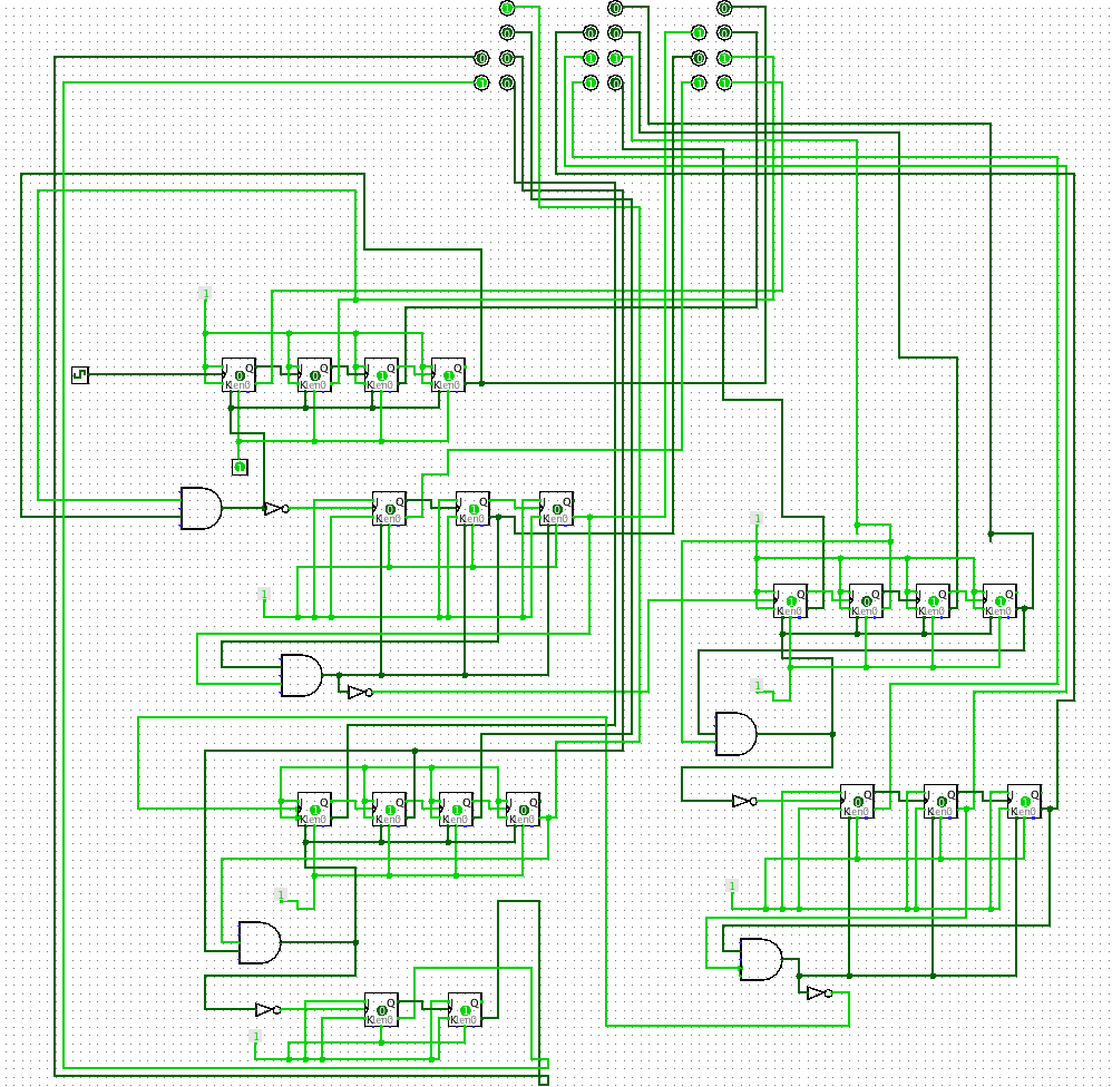
I've always been interested in clocks. I am a habitual watch wearer and I find the processing of timekeeping interesting. I came across the concept of the binary clock in my introduction to digital logic class where we talked about counters built around a clock pulse and edge-triggered flip flops. Below is my simulation of a binary clock using just JK flip flops and some simple logic gates. After building this simple simulation I was hooked and I knew I wanted to build a binary clock of my own in the real world. In this post I'll show you how I went about designing and building my clock around an Arduino Mega.
Logisim Binary Clock built from JK flip flops
Design
I wanted to create a clean and reliable design for this project, something that could be constructed fairly easily and could be built by others.
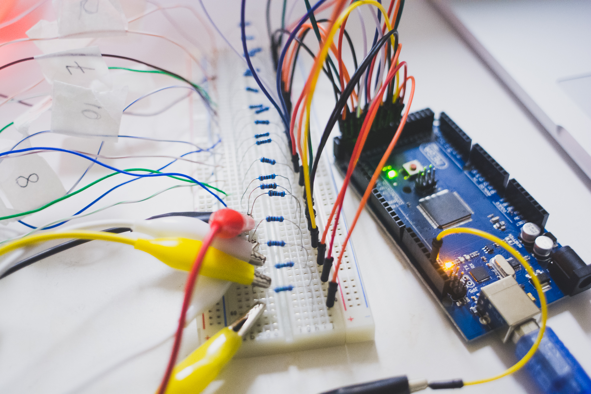
I first looked into building the clock using just 74 series logic chips, following the basic design shown in the above simulation, since I already understood how the above circuit functioned. I quickly found that going that route would require around 11 ICs. That is not an unmanageable amount by any means but considering that each IC required at least 8 connections it would most certainly become a rat's nest of wiring that I wanted to avoid. I then turned to Arduino. I decided to use the Arduino Mega since it would provide more than enough I/O for this project. While this project could certainly be accomplished with an Arduino Uno the implementation would require shift registers to increase the amount of useable outputs. For this stage of the design I wanted to avoid that extra layer of complexity. [Where I bough my Mega for $12.]
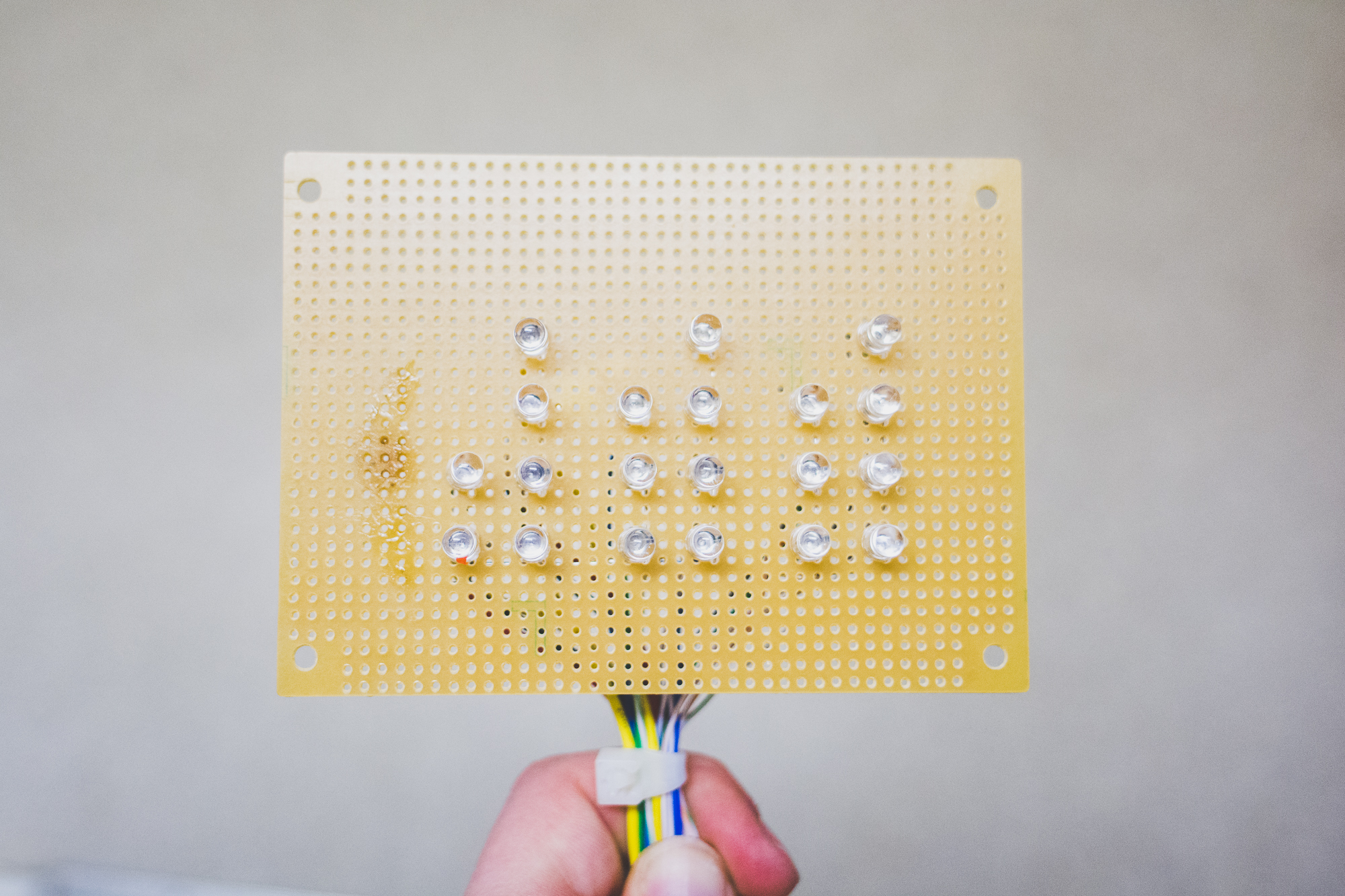
In order to help test my code before building the final clock I assembled this test LED display. This display could be connected to the Mega and used to debug any code before I went about building the final implementation. In order to ensure that the Mega would perform as desired I began developing some proof of concept code to use along with my test LED display. After a few iterations, I had some working code that counted up using the four bit binary numbers of my layout. Next, I used two SPST push buttons and a few more lines of code to allow me to increment both the hours and minutes of the clock. On power up the clock began counting up from zero, but with the inclusion of the two buttons I was able to set the clock to the current time. The timekeeping portion of my code is handled by the Time Library that includes functions to return the current seconds, minutes, and hours as well as a function to adjust the current time. This was key to allowing the user to update the time as well as ensure the Mega kept proper time regardless of where the program was in execution. This is explained in greater detail in the CODE section below.
Construction
After I was able to test my preliminary code with the LED display and the two push buttons, I moved on to constructing the actual clock. Below are some of the parts I used to build the clock and as you can see its just some simple 5mm LEDs, buttons, switches, and resistors. It's important that we include the resistors for each LED to limit the current for the sake of the life of the LEDs as well as the Mega. By using a 220 Ohm resistor we can limit the current through each LED to about 13.6mA. Each Mega pin can supply up to 40mA and a maximum of 800mA for the whole package (In this case the number is capped at under 500mA since I opted to power the clock via USB). If all twenty LEDs were on at the same time then we would be drawing 272mA, within our limits.
I began the construction of the clock by drilling the necessary holes into the enclosure for the LEDs on the front panel and the switches on the side. I prefer to create a layout of the holes needed and then tape it to the case so it is easy to ensure that all the holes end up in the right place. I chose to use a 5"x4"x3" metal enclosure from BUD Industries since it would be both sturdy and large enough to house all of the necessary connections. If you use a similar enclosure you can download and print out the drilling guides I used. In the image below you can see partway through the process of drilling the holes for the front panel. Once all the holes were drilled, the LEDs were placed into the front panel and then secured with hot glue. After the LEDs and switches were secured in the case I began the wiring process. I soldered a short wire to the anode of each LED and then wired all of the cathodes together using solid copper wire. Using a small protoboard I connected all of the anode wires to an individual resistor and then ran another wire from the resistor to respective digital pin on the Mega. For the switches 22k Ohm pull-down resistors were used. Once everything was connected it was time to compile the code onto the Arduino and finally test out the construction.
Code
The code behind the binary clock is fairly straightforward. You can view the complete code at the link below, which you can also download and compile onto your Arduino if you so desire. In this section I will describe the overall idea of what the code is doing by looking at some of the most important portions. Also, I would like to note that this code could be written more efficiently, particularly with the use of Arduino ports that would allow me to update the status of the 20 digital output pins by writing 8 bit numbers directly. For simplicity and ease of understanding I have written the current code using the common Arduino digitalWrite function.
Below is the main loop the Mega runs continuously after running the setup portion of code. I didn't show the setup block since it simply just initializes all the required pins for the I/O. The first thing the Mega does is check the status of the two time setting buttons. If the Minute Button is pressed, using the adjustTime function from the Time Library I mentioned earlier, 60 seconds are added to the system time. The same goes for the hour button. Next the two toggle switches are read. These were originally intended to be used for an alarm function but I later decided that I didn't have much use for it. Now I am planning to use those two switches to include two different display modes. The first simply lights up the LEDs on the front panel in a random pattern and my plan for the second switch is to use it to enable a sound visualizer.
void loop() {

  // get user input from push buttons
  if (digitalRead(min_button) == LOW) {
    adjustTime(60); // add 60sec or 1 min
    }

  if (digitalRead(hr_button) == LOW) {
    adjustTime(3600); // add 3600 sec or 1 hr
  }

  if (digitalRead(randomize_button) == LOW)


  if (digitalRead(wave_button) == LOW)


  // get new time and update display
  seconds = second();
  minutes = minute();
  hours = hour();

  UpdateDisplay(seconds, minutes, hours);
  delay(100);
}
After the Mega checks the state of all the buttons and switches, it sets the three variables that hold the current time by calling the second, minute, and hour functions from the Time Library. Once these values are updated, the function UpdateDisplay, shown below, pushes the new time to the LED display. This function works by breaking the input time into each individual digit. These digits will then be coded into binary. As you can see in the small portion reproduced below, I extract the ones digit with the % operator and then simply divide by 10 to get the tens digit. Once we have those digits, a switch statement is used to set the display and this is where the number gets converted to a binary-like pattern. If you observe the pattern (considering that led1 is the least significant bit) you can see when the ones digit is 0, all the LEDs are turned off, and then when the ones digit turns over to 1, we turn on led1. This pattern continues all the way up until 9, then we move to the tens digit. This process is repeated for the minutes and hours as well.
// take as input time in sec, min, hr as ints and then output to Binary LED layout
void UpdateDisplay(int seconds, int minutes, int hours) {

  /* Seconds Count */

  int seconds_ones = 0;
  int seconds_tens = 0;

  //find seconds ones and tens
  seconds_ones = seconds % 10;
  seconds_tens = seconds / 10;

  // seconds 0-9 counter
  switch(seconds_ones) {
    case 0:
      digitalWrite(led1, LOW);
      digitalWrite(led2, LOW);
      digitalWrite(led3, LOW);
      digitalWrite(led4, LOW);
      break;
    case 1:
      digitalWrite(led1, HIGH);
      break;
    case 2:
      digitalWrite(led1, LOW);
      digitalWrite(led2, HIGH);
      break;
    case 3:
      digitalWrite(led1, HIGH);
      break;
    case 4:
      digitalWrite(led1, LOW);
      digitalWrite(led2, LOW);
      digitalWrite(led3, HIGH);
      break;
    case 5:
      digitalWrite(led1, HIGH);
      break;
    case 6:
      digitalWrite(led1, LOW);
      digitalWrite(led2, HIGH);
      break;
    case 7:
      digitalWrite(led1, HIGH);
      break;
    case 8:
      digitalWrite(led1, LOW);
      digitalWrite(led2, LOW);
      digitalWrite(led3, LOW);
      digitalWrite(led4, HIGH);
      break;
    case 9:
      digitalWrite(led1, HIGH);
      break;
    }
Final Test
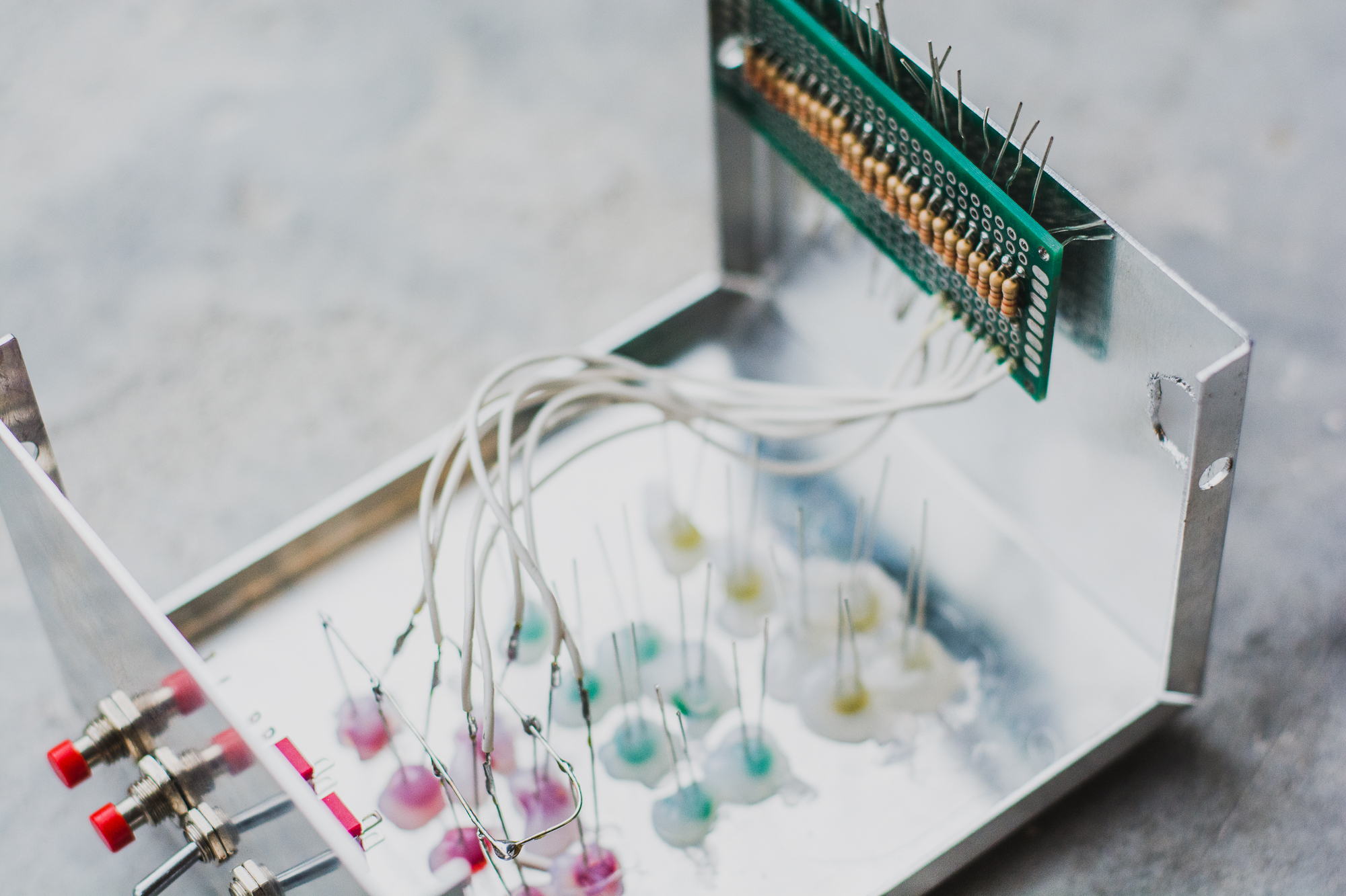
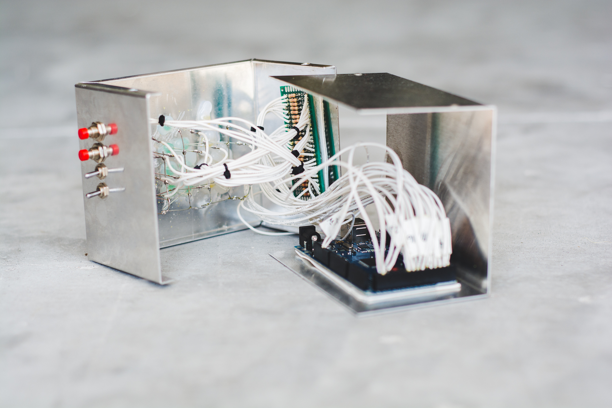
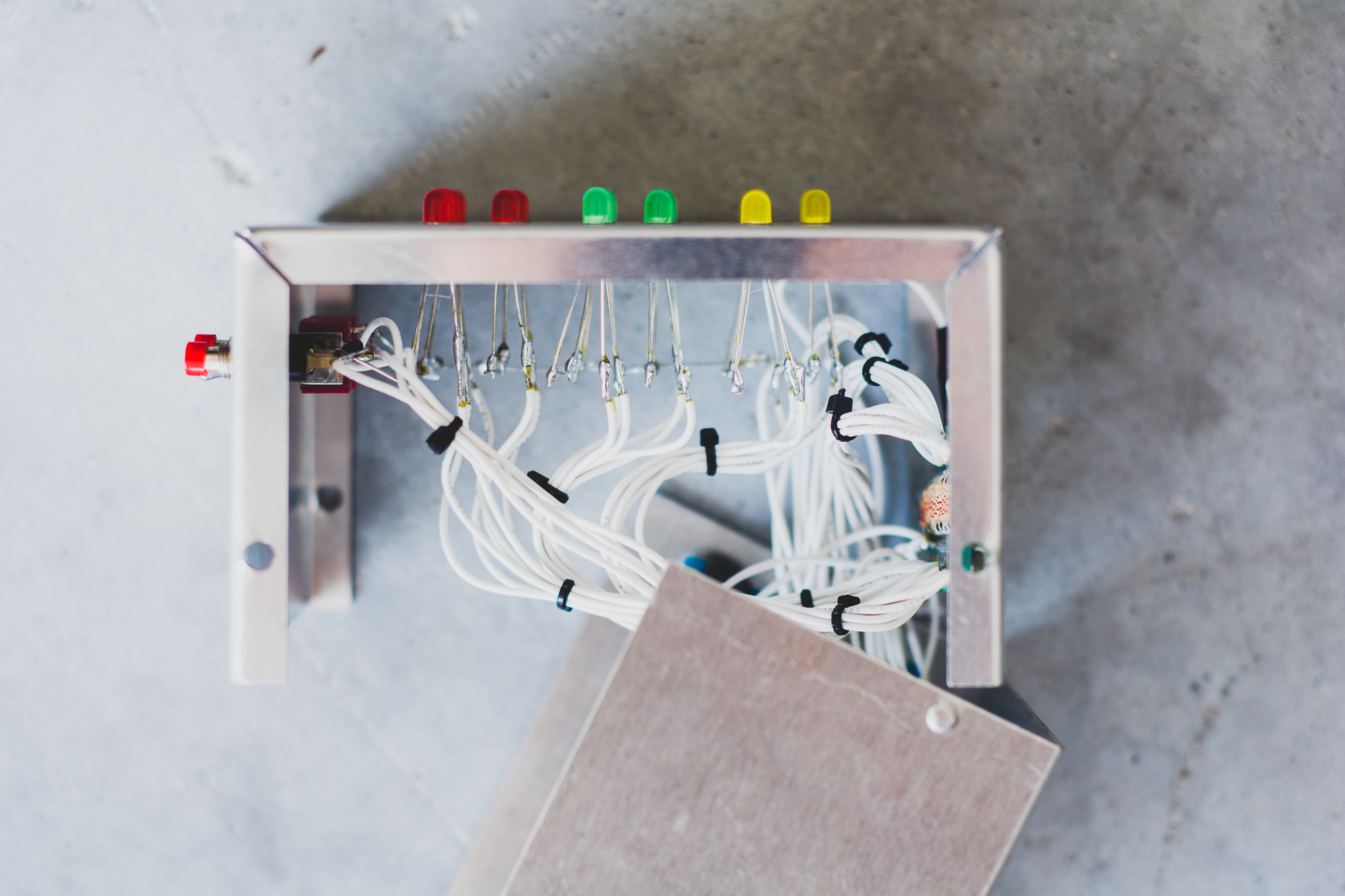
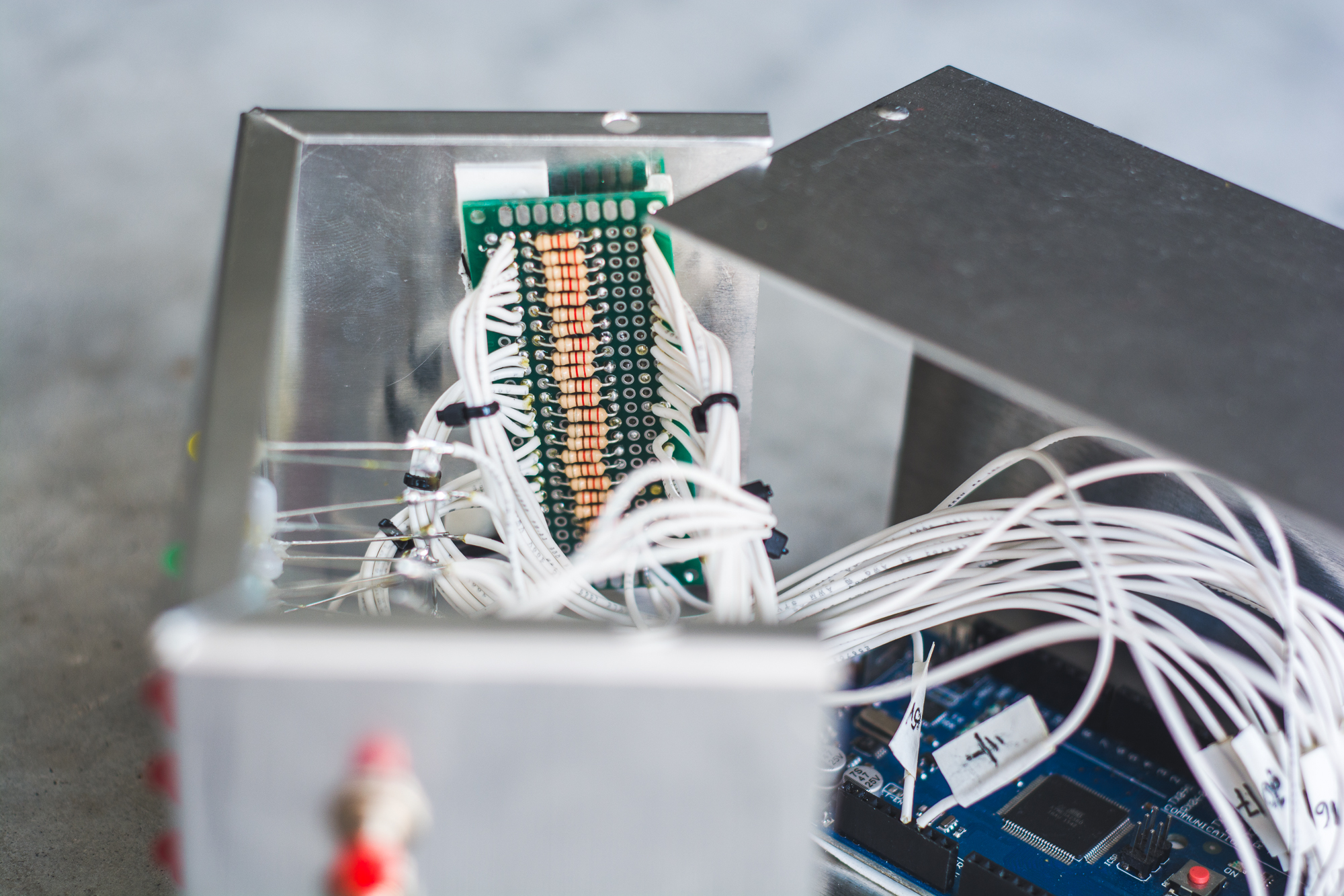
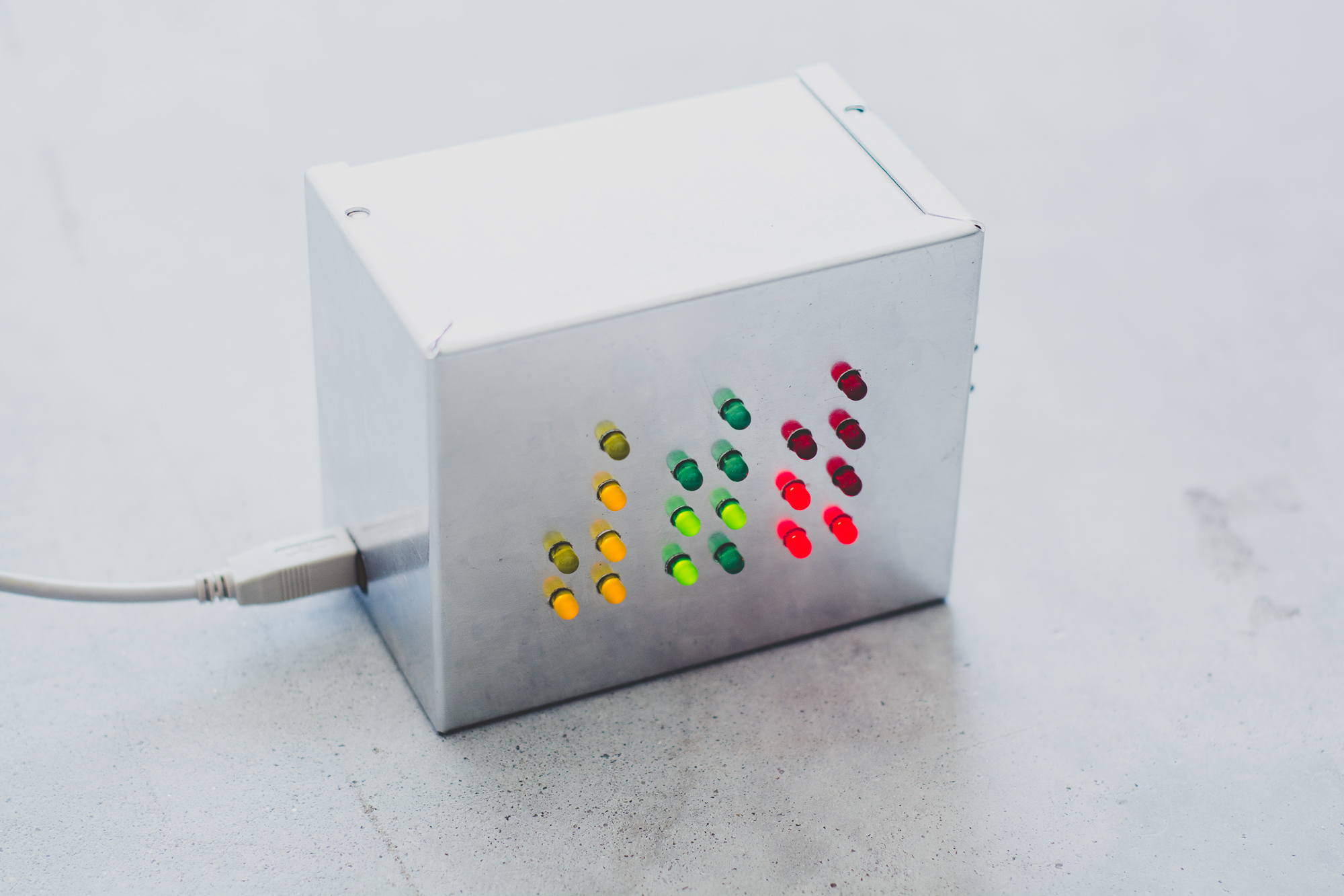
With all of the connections completed inside the clock and the code loaded onto the Mega it was time to test everything out. After attaching USB power, the clock began counting up from zero. Using the two push buttons I was able to set the time. The photos above show all of the internal connections and the final clock in action. As you can see there a number of wires and I used small zip-ties to try and keep the wires as organized as possible. I also ensured that all of the wires were long enough to allow me to easily open the case if some issue needed to be addressed. Both the resistor board and the Arduino were secured to the case using double sided foam tape that isolates the contacts, stopping them from shorting out on the case, as well as secures the boards in place. In the short video below you can see the clock in action. It shows the basic timekeeping functionality of the clock, along with the time setting and randomize mode.
Future Development
This is simply the first working version of the LED binary clock and I plan to add upon the work done in this preliminary project. Most of the future development lies in the Arduino code. As I mentioned before, there is ample opportunity to make the code more efficient than it currently is. In addition, while the randomize function was simple enough to implement, the music visualizer will be more complex to implement and will obviously require the inclusion of additional hardware. I have also considered the possibility of adding a Real Time Clock board to improve the timekeeping of the Arduino. An even better option might be to develop code to allow the clock to update its time over USB. Expect to see future updates soon.
