Introduction
The humble monitor controller is many times an overlooked component of a recording studio setup. The volume knob is such a ubiquitous interface in our lives that we very often take its design and function for granted. In reality, great care must be taken in order to implement an effective and transparent volume control.
The largest issue with any device that we wish to add into our signal chain is the resulting effect it imparts on the signal as it travels from its source to its destination. In this case the source is most likely an audio interface and the destination is a set of studio monitors. Passing our signal though any hardware is going to affect the signal in some way no matter how we engineer the device, yet certain designs will have a more significant impact than others. In the case of commercially available monitor controllers on the lower end of the price spectrum (ex: Mackie Big Knob and Behringer CONTROL2USB), they generally implement active circuitry to handle the attenuation of the signal but also offer additional features and usually multiple inputs and outputs. At the middle of the spectrum (ex: PreSonus Central Station), we have systems that offer the additional features but retain a passive signal path for the audio. This offers a good compromise as you retain the features and input/output switching, but keep the signal path as free of distortion as possible. At the highest end of the spectrum there are a number of options that work in the digital domain and offer precise A/D and D/A as well as intensive level matching, in addition to a slew of other features. Less commercially popular are totally passive devices that are used for source switching and volume control (ex: NOS McONE). The passive controllers have interested me the most due to their simplicity. This simplicity aligns well with the final goal of designing a piece of hardware that imparts minimal distortion onto our signal, uses the smallest amount of circuitry, and can be implemented at a very low cost. Therefore it was from here that I drew my design inspiration.
Mackie Big Knob PreSonus Central Station NOS McONE
Design
To begin the design process I first decided on what features I wanted the controller to offer. Nearly all of the commercially available devices allow for multiple inputs to be selected as well as multiple output paths to be routed to separate monitor systems. In my setup I use my audio interface as the sole source in my system (as I can easily patch any analog sources though the interface) and since adding this capability adds wiring complexity as well as cost, I opted to feature a singular, balanced stereo input as well as a singular, balanced stereo output. In order to accommodate the desired small form factor of the controller, TRS connectors were chosen for the input and output connections, but XLR connectors could have been implemented if space and price were not as much a concern.
Monitoring mixes in mono can be an important tool for determining and analyzing the stereophonic and phase content of a track. Many times monitor controllers provide an option to sum the incoming signal to mono and then feed that signal to the monitors. This can be achieved in a passive design but obviously requires a bit of extra circuitry to achieve. Since the summing occurs in the analog domain there will be both constructive and destructive interference, which will on average result in a +3dB increase in the output signal. That means when switching between the stereo and mono mixes there will be a level imbalance. This level imbalance makes hearing subtle differences in the mix more difficult between the two. For that reason, coupled with the fact that most interface controllers feature a sum to mono option for monitoring (as does my Focusrite Pro 40) in the digital domain, I decided to keep the design simple and feature just a volume control and mute toggle.
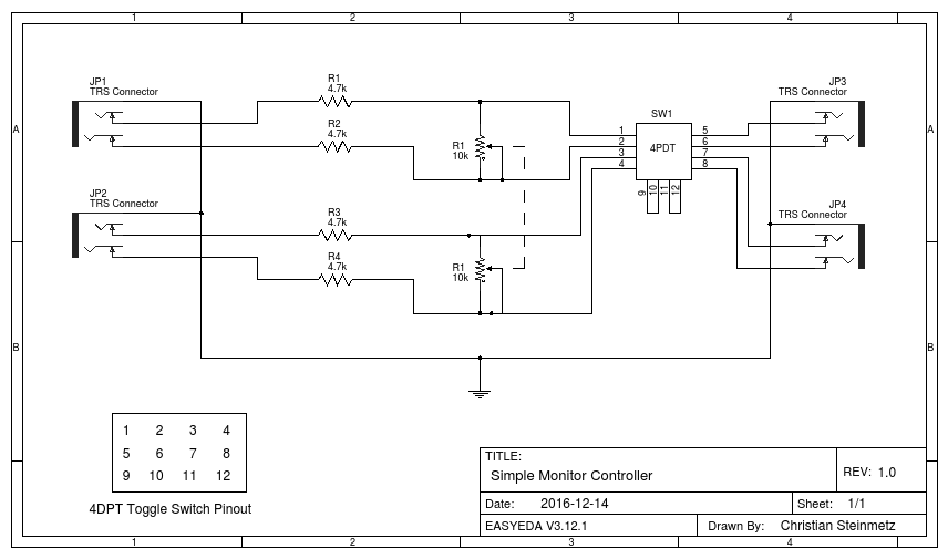
The design here pulls from the design for a passive monitor controller from JLM Audio. This article is certainly worth a read and touches more on the operation of a monitor controller as well as additional configurations and features possible. As shown below, the controller consists of a resistive attenuator pad with a dual gang potentiometer. The paired resistors in the network will result in a line attenuation of about 6dB and the potentiometer will be responsible for the remainder of the attenuation. To learn more about the operation of the attenuator see this article on the math behind fixed resistor attenuators. Following the output of the attenuation section is a four pole double throw toggle switch (4PDT) that connects the TRS outputs to either the signal coming from the potentiometer or shorts together pin 2 and pin 3 in order to produce the muting effect. See the schematic below for more details about the circuit.
Parts
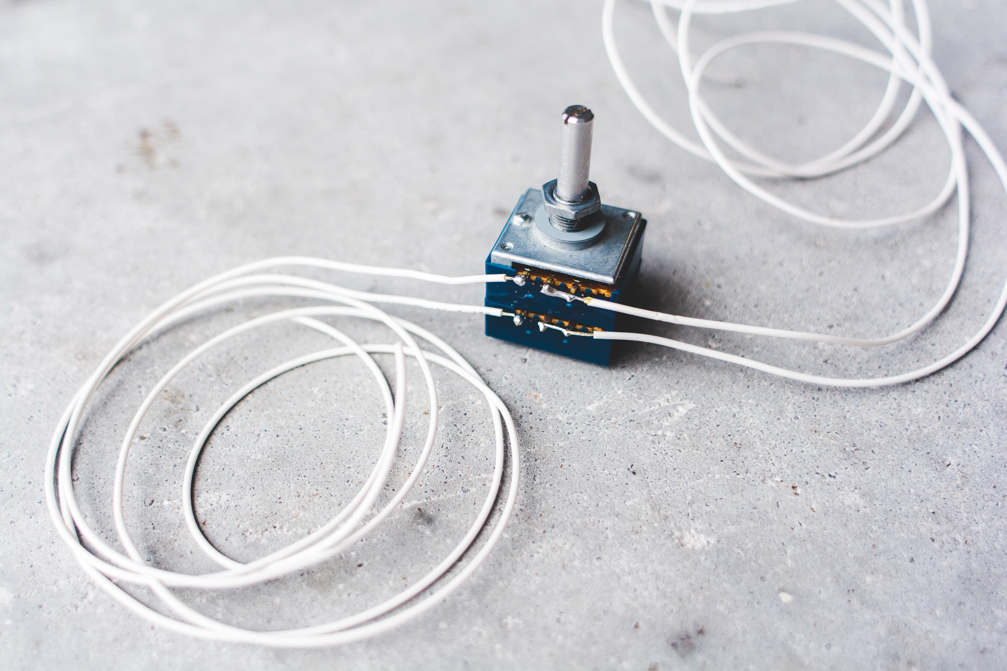
Being a simple circuit by design, the finished product requires a minimal number of parts. At the center of the controller is the ALPS 10KAX2 10kΩ dual gang potentiometer. Any 10kΩ dual gang pot can be used but in order to achieve good tracking between the left and right channels at lower volumes, precision construction of the pot is critical. ALPS has been known for their high quality and well matched dual gang pots and that is why they have been used extensively in high quality audio applications. Some kind of knob will be needed for the pot in order to enable the user to easily adjust its position. A heavyweight aluminium knob was used in this case to achieve a smooth action.
ALPS 10KAX2 10kΩ dual gang pot
Following the input signals are four 4.7kΩ 1% 1/4W metal film resistors. The matching of these resistors is important if we wish to retain the high common mode rejection of the balanced signal. Any variation in resistance will result in a difference in voltage drop in relation to the hot and cold signals. Therefore resistors with a 1% tolerance were used and they then were manually screened to find four resistors that all were within +/- 10Ω of each other.
4.7kΩ 1% 1/4W Metal Film resistor
In order to implement the mute switch a 4PDT toggle switch was used. This allowed the connection of the four signal carrying conductors for both channels of balanced audio and then enabled the switch to connect them either to the output or to short the hot and cold for each channel in order to implement the mute function.
4PDT Toggle Switch
The final components of the controller were the four 1/4" female TRS connectors placed on the back of the enclosure. The first set allowed for the connection of the incoming signals from the audio interface and the second set carried the attenuated signal for output to the amplifier or powered monitors.
1/4" TRS connector
Construction
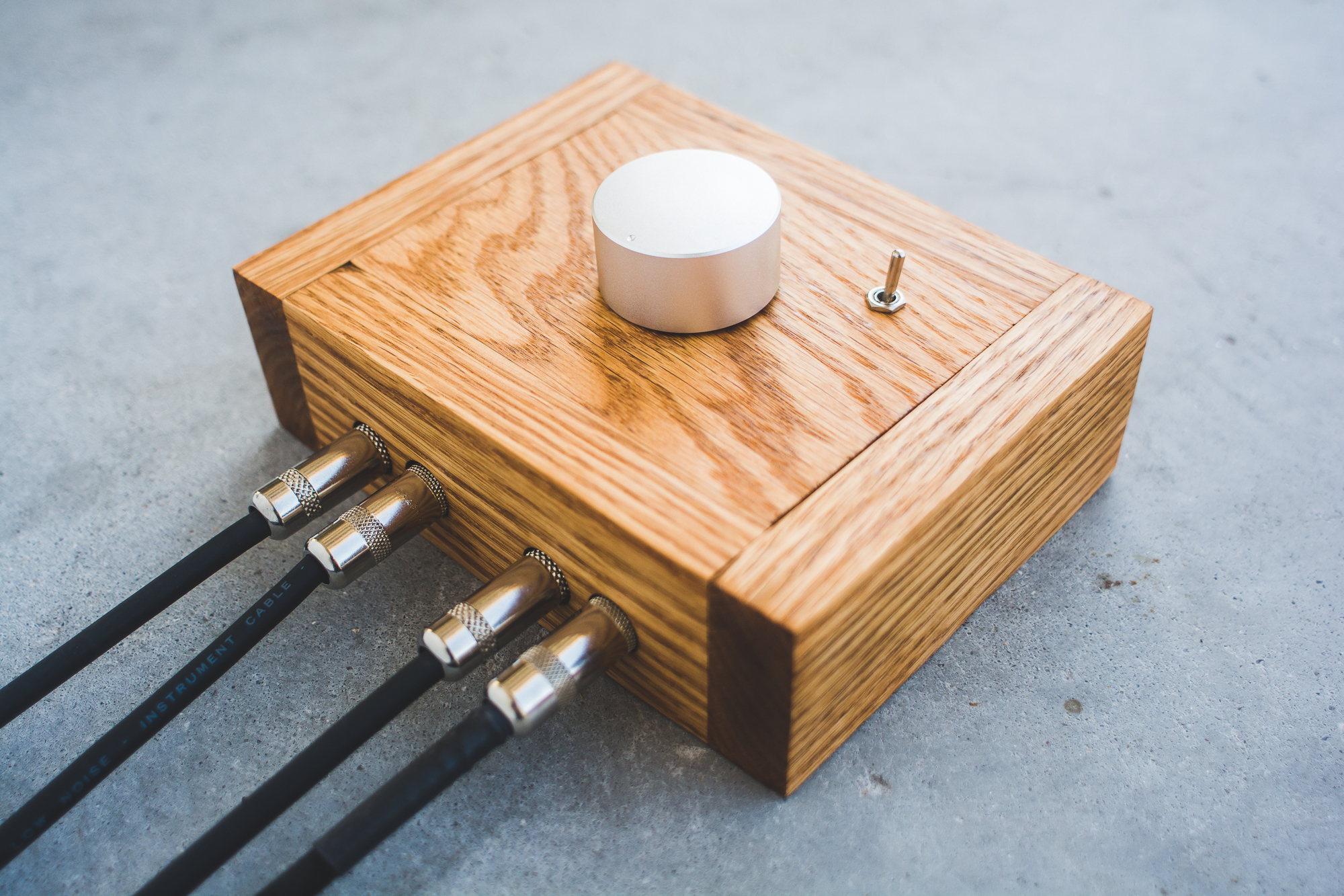
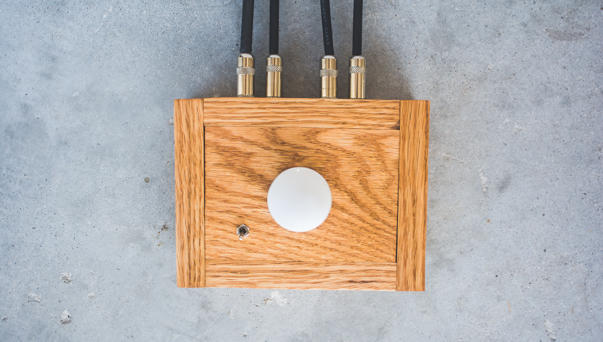
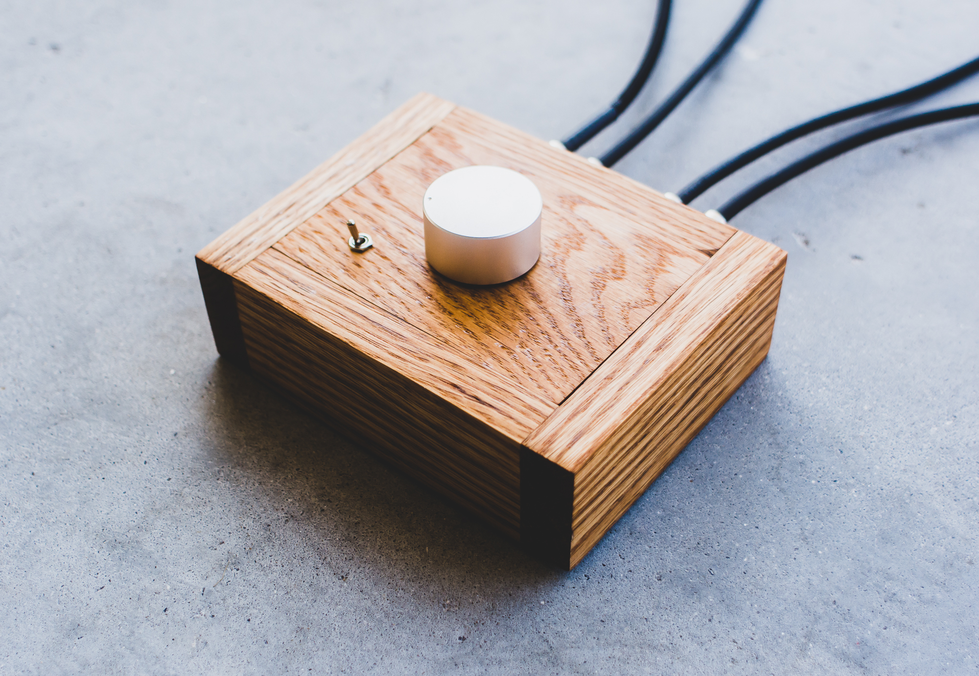
With the circuit design complete the construction of the enclosure needed to be determined. Obviously any enclosure that keeps the internal components safe from damage and keeps the electrical connections away from the user will suffice. There is also a desire for ergonomics as well aesthetics. In this case a simple wooden enclosure was designed and built to house the components.
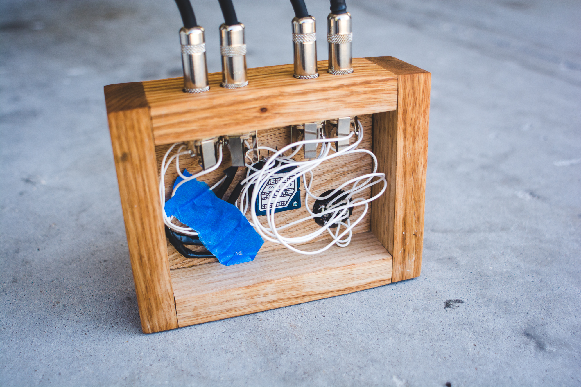
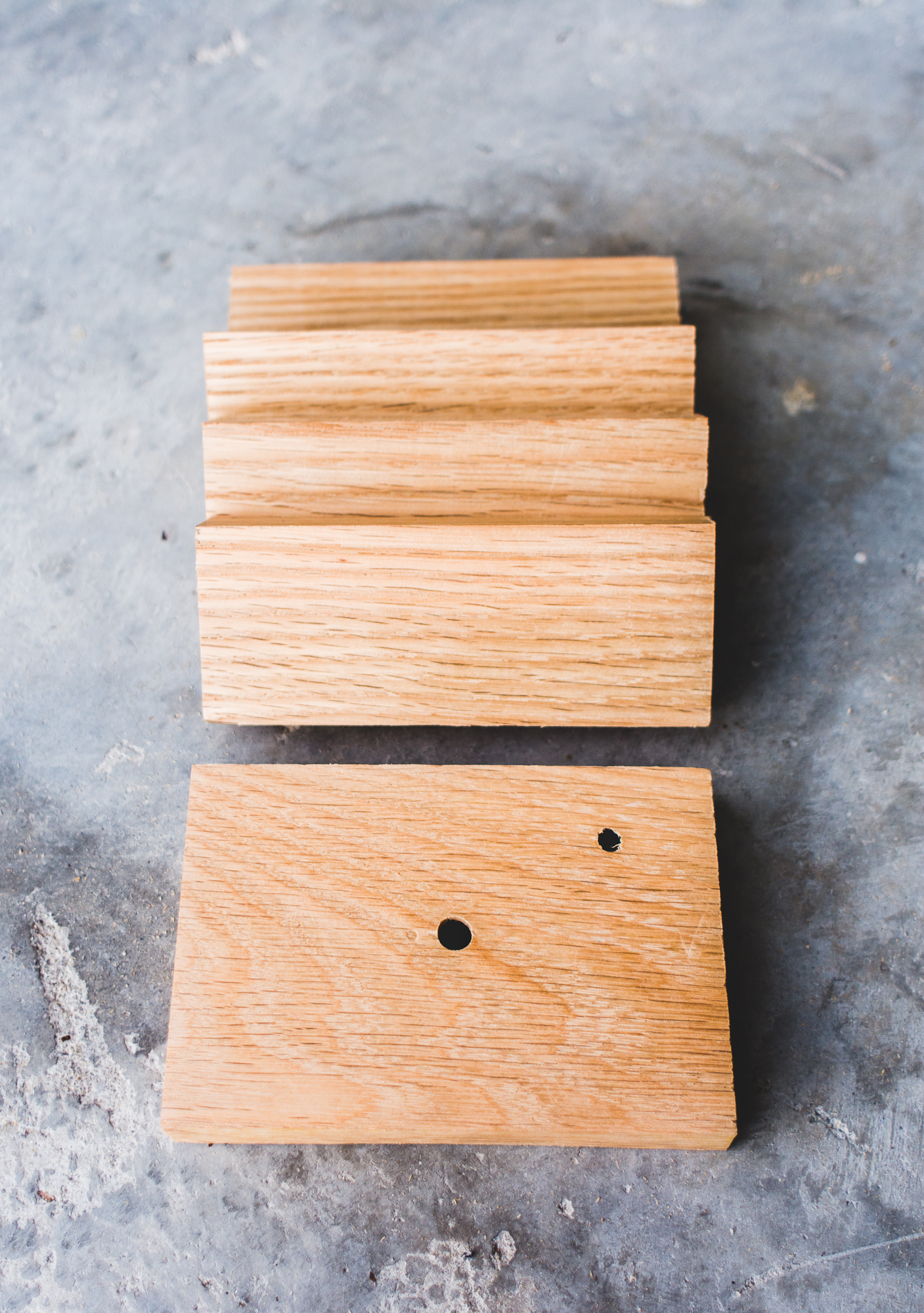
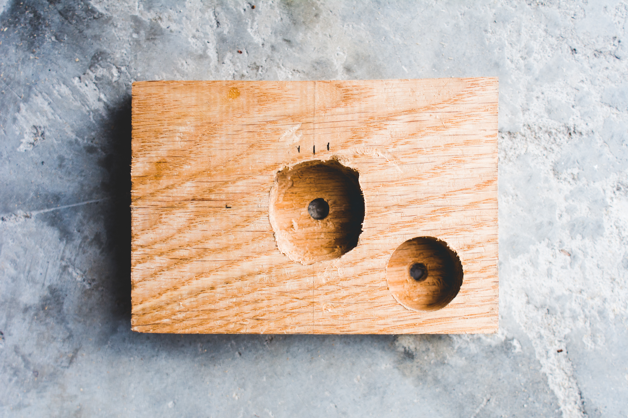
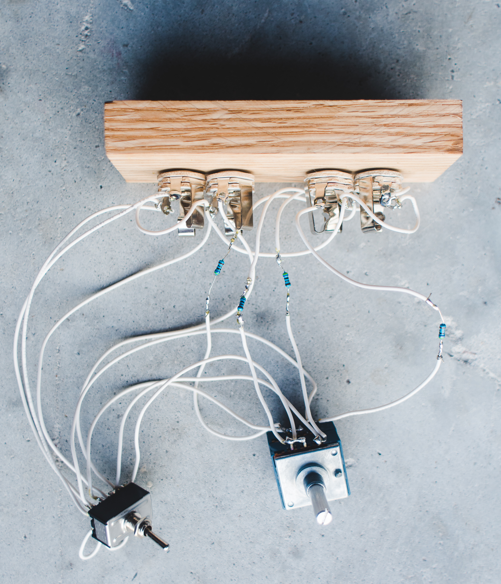
The enclosure consists of four pieces that measure 5” x 4” and make up the sides and then a top piece that measures roughly 3” x 5”. Since a ¾” piece of red oak was utilized to make the enclosure, spade bits were used to drill out the needed space beneath the top panel to accommodate the hardware on the front. You can see this in the images below. Due to the tight space within the enclosure, the electronic connections were made prior to assembling the box. Once the connections were made according to the schematic the box was assembled using wood glue and some clamps. With the enclosure assembled it was then sanded and stained.

Conclusion
Testing the controller revealed that is was successful in attenuating the stereo signal as expected. The design in this monitor controller was deliberately kept extremely simple. While the design was simple and the parts list was short, care needed to be taken in order to achieve a volume attenuator that would produce desirable results and impact the audio signal the smallest amount possible. An audio system is only as good as its weakest component. If you enjoyed learning about this project make sure to check back periodically to read about updates.
