Introduction
Old ATX power supplies are readily available, either from old computers that have yet to be disposed of, or from electronics recycling centers. Instead of discarding these power supplies many people have turned their old ATX supplies into simple bench top power supplies for use with small electronics projects. ATX supplies make great candidates for this since their internal circuitry already produces a number of common DC output voltages, e.g. +/- 12V, +/- 5V, as well as +3.3V.
The process of converting the supply is quite simple and straightforward. All that must be done is, first, the connection of dummy load to trick the on-board protection circuitry into thinking that is it connected to a load (which would normally be a motherboard when used in a computer), and then second, the inclusion of external binding posts so that the desired output voltages can be easily accessed and used. While it is not necessary if the supply has a power switch, a secondary power switch can be added to control whether or not the supply will turn on and begin supplying voltage to its output terminals.
PIN Identification and Wiring
The first step in the process is to open up the ATX power supply and identify a few key connections as well as determine what voltages the power supply currently generates. Most supplies follow a common color convention for all the connections and the respective voltages they carry, although some manufactures have been known to deviate from these standards, most notably Dell. The image below shows the common convention for both the 20 and 24 pin connectors. At this point it is important to take note of what voltages will be used for the final supply as well locating the green, PS-ON, wire. This wire will be used to implement the power switch.
Color conventions for both 20 and 24 pin ATX connectors
If a power switch is not desired, the green PS-ON wire may simply be connected to any of the available black, ground wires. When the PS-ON wire is pulled low it signals the supply to turn on and begin to output voltages. A simple single-pole single-throw (SPST) toggle switch can be used for this task and in the case of my design I simply reused a DPDT switch that had been salvaged.
The next step is to wire in the dummy load. Here a 10Ω 10W power resistor was used. One of the red wires, carrying +5V, was connected to one end of the resistor and the other end was connected to one of the ground wires. Then as shown in the photo below, the resistor was mounted to grill of the case with a zip tie. It is good practice to ensure that the resistor is placed in such a way to facilitate cool operation as it may heat up.
Add Binding Posts and Testing
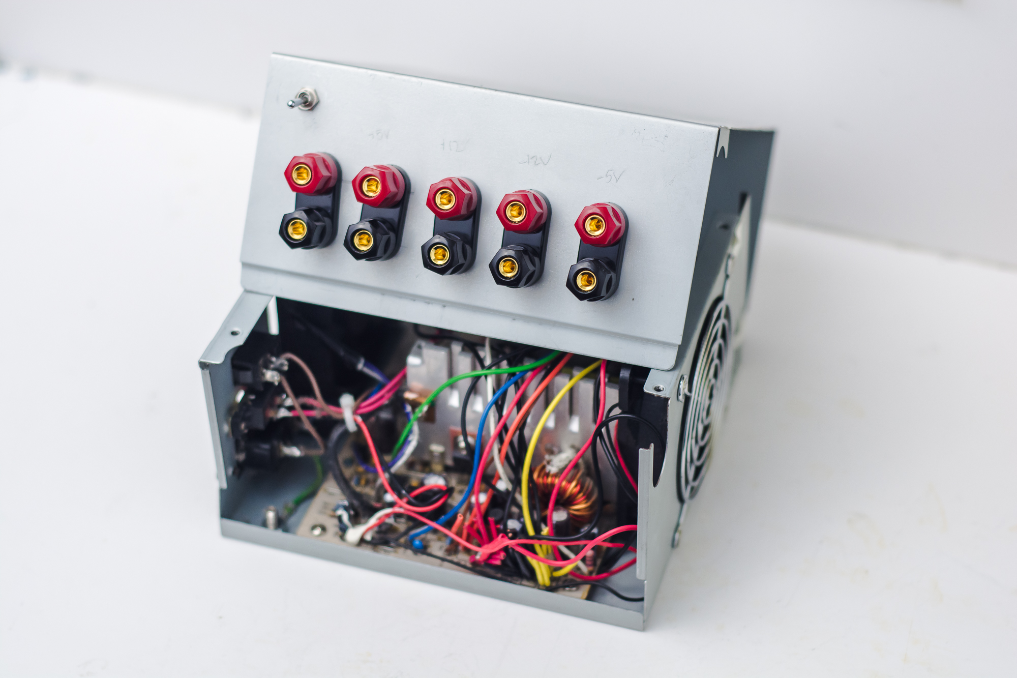
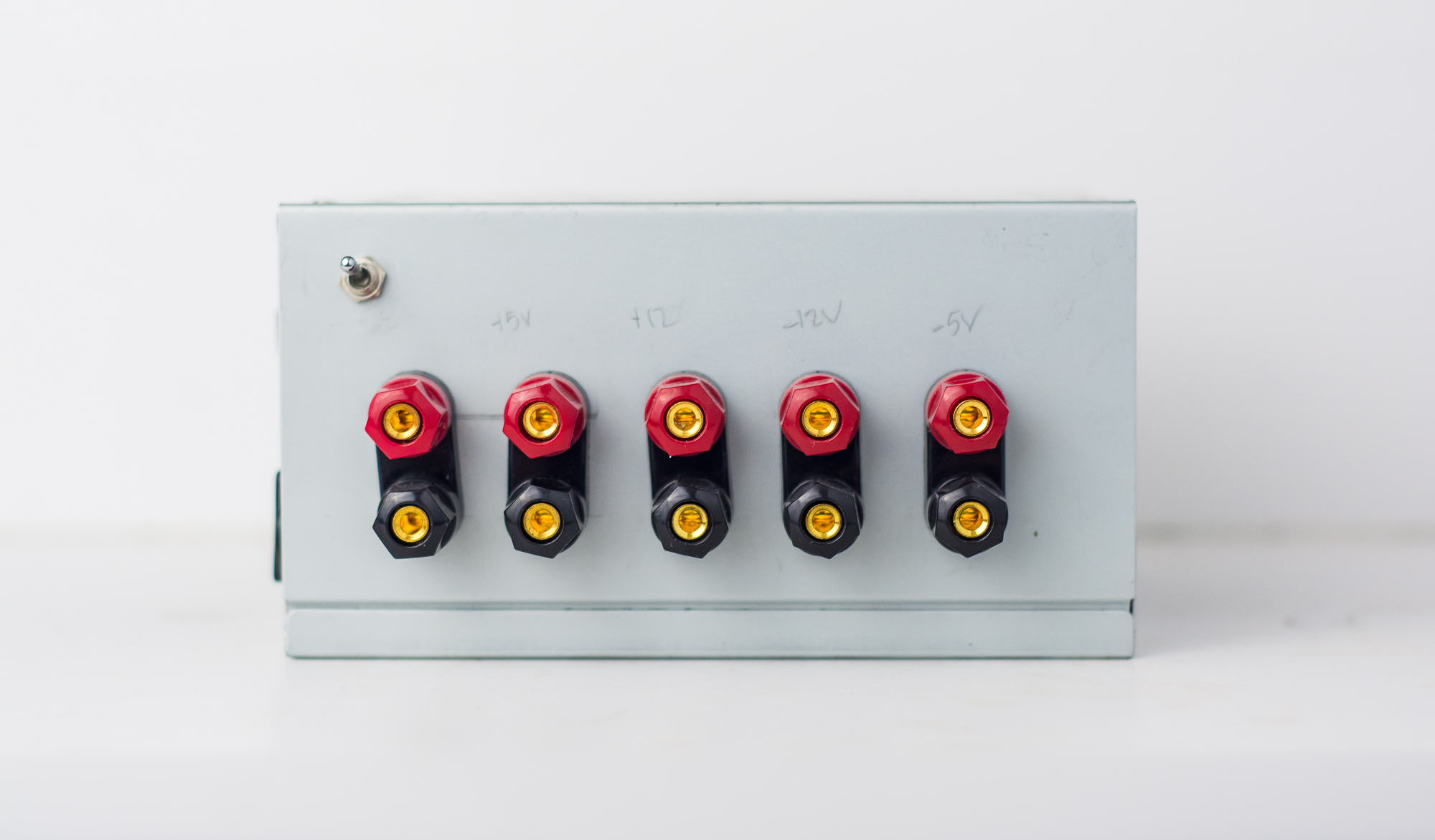
Once the power resistor and switch are in place, when the supply is plugged in and powered up voltages will be supplied to the appropriate connections. In order to make the internal supply voltages readily accessible for use in other projects, binding posts can be mounted to the existing ATX power supply case and then connected to the different voltage outputs. Holes were marked and then drilled for the binding posts and power switch and then the binding posts were mounted to the chassis. Note that it may be difficult to close the case if the binding posts interfere with the preexisting components in the supply. Make sure to test out how the binding posts will fit before choosing where to drill.
With the bindings posts installed its time to connect the appropriate voltages. In the case of my design I used the available supply voltages of +5V, -5V, +12V, -12V, and +3.3V. It is important to note that not all of these voltage outputs are capable of delivering the same current. Make sure to check the specifications of your supply to determine this. In general the +5V supply will be capable of supplying the greatest amount of current (this particular supply was rated at 24A). The selected wires can easily be soldered to the binding posts that have been mounted in the case. Also, as can be seen below, one ground wire was connected to each binding post ground. Note that for the +3.3V output in this particular supply it required that two separate wires be connected in order for the correct voltage to be produced. Once all the voltages are connected its time for the supply to be powered up and for all of the output voltages to be tested to ensure everything is wired correctly and operating as expected.
Considerations and Precautions
Assuming everything is working as it should, you now have a fully functional multiple output, constant voltage, DC power supply. This is a very simplistic build but there are a few things to watch out for when making this modification. The first is to be very cautious when dealing with the supply outputs. These devices are capable of generating large amount of power that could easily be harmful. It goes without saying that you should always power down and disconnect the device from mains power when you have the device open or any exposed leads. Also, it is important that the binding posts be isolated from the metal of chassis. When I first installed the binding posts some of the rods of the terminals touched the metal case and caused the device to short and trip the short circuit protection, turning the supply off. I was then able to isolate the terminals with tape and hot glue, checking the connections for and unwanted continuity with a DMM.
Future Improvements
There are a few features that could easily be built to add extra functionality to these hacked power supplies. The easiest would be to add some indicator LEDs and simple logic circuitry to help display the state of operation. A red LED could be lit when a fault occurs and the supply cuts the voltages out and a green LED could be used to signify that all of the outputs are active and the power supply is operating as it should. Also, it would be useful to integrate a voltage regulator of some kind that could be used to vary one of the positive supply voltages over a smaller range. The inclusion on a simple seven-segment display to show the current voltage output of the regulator would help as well. Keep a look out for these updates in the future.


